![]()
![]()
![]()
|
|
|
|
Physicians trained in cross-sectional imaging are able to understand the spatial relationship between tissue structures by mere exploration of cross-sectional slice images. However, for communication purposes it is often helpful to generate simulated views of isolated objects of interest from different viewpoints. 3D image processing allows to derive such objects from slice images and calculate virtual reality scenes which can be explored interactively.
Surface Rendering (SR)
One way to derive a virtual object is to track (segment) an organ boundary in the slice images, build a 3D surface from the contours, and shade the surface. The P3D tool supports such segmentations by applying thresholds and/or region growing, optionally restricted within volumes-of-interest. As a special option, the object can be colored by projecting the information of matched images onto its surface (texturing), even animated in time. This feature allows, for instance, to visualize the concentration changes of the NH3 perfusion tracer at the myocardium surface throughout a dynamic acquisition.
Volume Rendering (VR)
A different way to derive a virtual object is to take a certain viewpoint in front of the object, cast rays through the object and record the ray values when the rays pass a plane behind the object, thereby producing an image. The ray value recorded in the image plane is a combination of the values in all the pixels met along the way from the viewpoint to the image plane, thus the name Volume Rendering. Typically, the combination is just the sum of the pixel values, each multiplied by a certain weighting function, called opacity. The result depends heavily on the image values and the opacity function. There are very successful configurations available for contrast enhanced CT examinations which provide the illusion of a three-dimensional representation, especially if the viewpoint is interactively changed.
Combination of 3D objects from Matched Series
A unique feature of P3D is the ability to combine and manipulate different types of virtual reality objects (VRO) in one common scene, even when they stem from different studies. Once a scene has been created, it can be saved in a VRML format file (SR objects only). These files can later be loaded into P3D (or an external VRML-Browser) to continue scene exploration. It is in principle also possible to import VRML-scenes from some dedicated 3D rendering programs and combine them with P3D objects, but the import may sometimes fail. So far, AMIRA data has been successfully imported.
CAUTION: When combining multiple studies in a single rendering, please match beforehand all images series in the PFUS tool and save the resampled images. Otherwise, unexpected shifts between the objects might occur in the scene.
Hardware Requirements and Performance
The P3D tool is based on the OpenGL implementation in the Java3D library. Therefore, using P3D requires a graphics board which supports OpenGL, preferably with at least 512 MB video RAM to accommodate high quality texture displays. As the 3D rendering implementation in Java3D is quite memory demanding (particularly with VR), a 64-Bit operating system and a RAM size of at least 4GB is highly recommended when working with highly resolved or dynamic data. We strongly suggest that you test P3D on your platform with your own data before purchasing this PMOD option.
An automatically Acceptance test is taking place when P3D module is first started. There are several 3D scene available for visual inspection and a dialog window opens for each scene. Please answer the questions and do not perform any other operation until test completion.
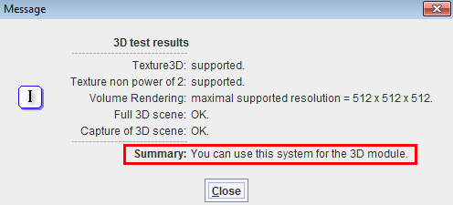
The following tests are performed:
At the end of all steps the test results will be summarized in a message window. If the test succeeded the results should be similar like the one below:
Starting the 3D Rendering Tool
The P3D tool is started from the PMOD ToolBox by clicking the button.

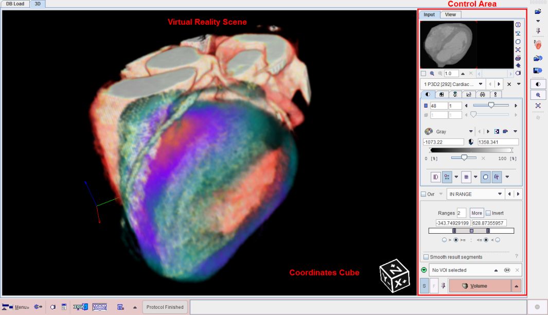
The P3D application window consists of a large display area for showing the 3D scene, a control area organized by the two tabs Input and View, and a detachable taskbar with shortcuts along the right edge.