Processing of a Static Scan
The processing of static scans is much simpler than a full functional quantification, because kinetic modeling is not applicable. However, PCARD can generate a polar map and a numeric table of the uptake values.
Static Scan Processing
- Load the image data in either row.
- Perform the automatic short axis reorientation, with manual adjustments if needed so the the orthogonal slices confirm a standard position.
- Define the five markers in the apex and at the basal locations using
 .
. - Activate the automatic contouring.
- Check the position of the Myocardium contours in the VOI tool and adjust them if necessary.

- Select the Statistics Button to start the segmentation process. The result is shown on the Kinetic Modeling page which has a slightly different configuration as illustrated below.

The table to the left contains the average uptake values in the different segments. The polar plot in the middle shows the uptake values obtained by the polar sampling process, and the images to the right illustrate the contour placement. Note that if you click into the polar plot, the image to the right is adjusted so that the corresponding slice is shown. With an orthogonal layout, the cross is positioned at the sampling location corresponding to the polar plot point. - Print the summary report using the REST (or STRESS) Report button, and save the numeric values using the Save Results button (switch button from REST Report to Save Results).
- If you need the values of the individual samples in the polar use the button Copy polar samples of individual sectors to Clipboard, and then paste into a program such as Excel for further processing.
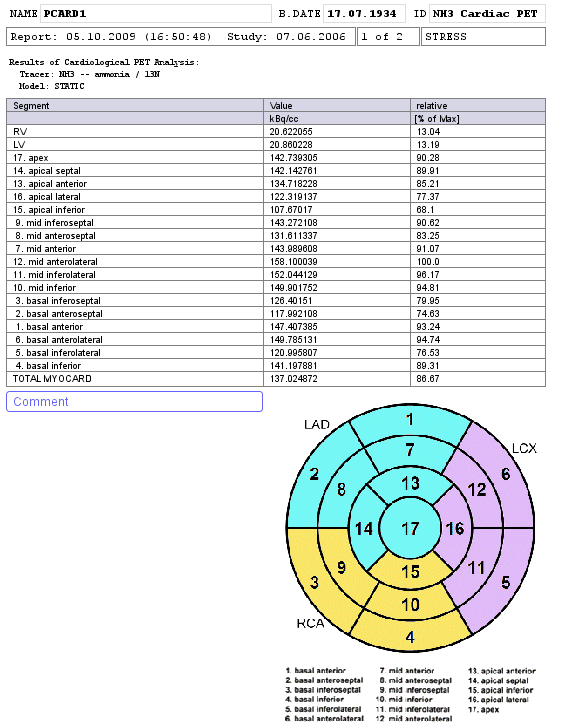
Page 1 of the REST (or STRESS) Report contains the segmental uptake values. To allow a quick overview a column with the percent uptake relative to the maximum has been added.

The polar plot is available using the Polar Plots report button.


